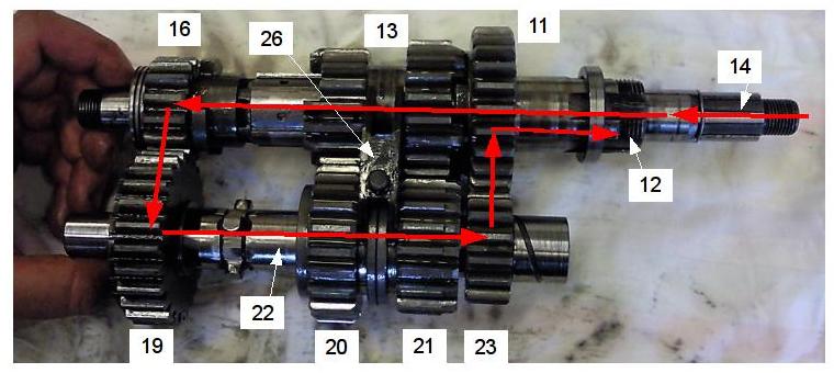
Previously, I've wondered how the gearbox really works and now that I have it apart, I could figure it out. I thought I write it down so other people could get an idea without taking it apart.
The numbering is identical to the Snidal's Workshop Manual and the Factory Manual.
There are three shafts: the mainshaft (14) which transmits the rotation from the clutch into the gearbox; the layshaft (22) which transmits the rotation of the mainshaft to the countershaft (12, aka mainshaft sleeve) in all but fourth gear. The the mainshaft turns inside the countershaft, which is, as the other name suggests a sleeve. The sprocket of the secondary chain is fixed to the countershaft. The mainshaft turns clockwise, layshaft counterclockwise and the countershaft again clockwise (as does the wheel), as seen from the side of the gearbox (not from the primary drive side).
There are four kinds of pinions:
The gear is selected by movement of the gear operator fork (26) which moves the pinions 20,21 (on the layshaft) and 13 on the countershaft. The fork is moved by the bellcrank (30, aka gear operator).

The gear operator fork (26) is to the far right (as seen in the figures, corresponding to the left hand side of the motorbike). Pinion 16 turns 19, the layshaft transmits the rotation onto 23, which turns 11. 11, being rotatable, is interlocked with the sliding gear (13) and thus transmits the rotation to the countershaft. Pinions 20 and 21 rotate due to the rotation of 13 but do not actually contribute anything.
Gear ratio:
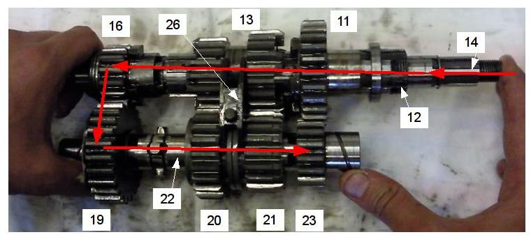
The fork (26) is a bit further to the left and thus the pinion 11 is not interlocked with the slider gear (13) anymore. As the Pinions 20 and 21 still rotate freely, no rotation is imparted onto the countershaft.
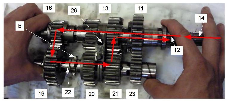
The layshaft is rotated by pinion 16 turning 19. The fork (26) is again a bit further to the left which causes the protrusions (marked a in figure for 3rd gear) on the right of the layshaft to lock into the pinion 21. 21 then transmits the rotation on to the slider gear (13) and thus the countershaft. Note that:
Gear ratio:
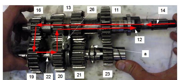
The layshaft is rotated by pinion 16 turning 19. The fork (26), again further to the left, such that the protrusions (marked b in figure for 2nd gear) on the left of the layshaft lock into pinion 20 which turns the slider gear (13) and thus the countershaft.
Gear ratio:
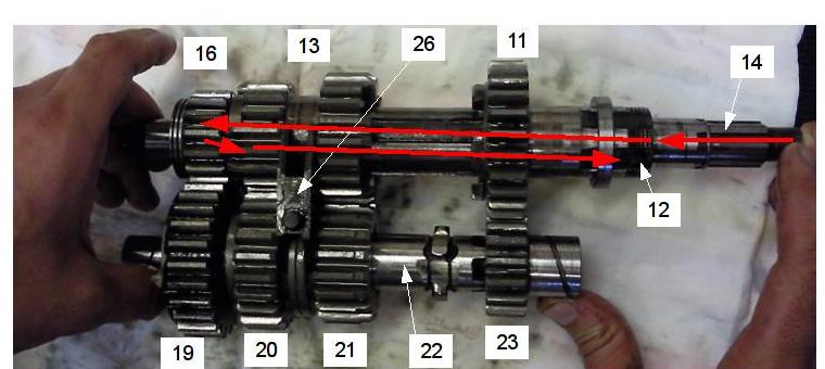
Even though the layshaft is still rotated by pinion 16 turning 19 it has no effect in fourth gear. The fork is to the far left and neither pinion 20 nor 21 are locked to the layshaft, nor is pinion 11 locked to the countershaft. However the slider gear now interlocks with pinion 16 and thus the countershaft rotates at the same rate as the mainshaft.
Gear ratio:
They are needed in-between gears as otherwise, during the shifting operation, two gears would be selected at the same time, causing the gears to lock up.
The gearbox needs to be in neutral for the kickstart to work as otherwise not only the engine is turned but also the rear wheel. The kickstarter pawl (34) grips on the inside of pinion 19 and turns it counterclockwise. 19 turns pinion 16, thus the mainshaft and with it the engine.
Mauro Werder 2009-07-14